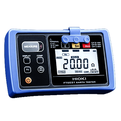
Fluke 1625-2 GEO Earth Ground Tester
Advanced Ground Testing for Reliable Electrical Safety


The Fluke 1625-2 GEO Earth Ground Tester is a professional grounding measurement instrument, making the Fluke 1625-2 GEO Earth Ground Tester Price in Bangladesh an important search for electrical engineers, testing professionals, contractors, and industrial maintenance teams. Designed for comprehensive earth ground evaluation, it helps professionals assess the performance of grounding systems and identify conditions that may require inspection or corrective action. Grounding plays a critical role in electrical safety because it provides a controlled path for fault current and helps protect people, equipment, and infrastructure. The Fluke 1625-2 is suitable for commissioning, preventive maintenance, troubleshooting, and periodic inspection of grounding installations. Its professional design makes it appropriate for demanding field environments where dependable measurement and practical operation are essential. Whether used in an industrial facility, power installation, commercial building, or infrastructure project, the instrument can support engineers in making informed decisions about grounding system performance. It is particularly valuable for organizations that require a dependable solution for routine electrical safety assessment and professional ground testing.
The Fluke 1625-2 GEO Earth Ground Tester provides a comprehensive approach to evaluating grounding and earthing systems. Ground resistance is an important electrical parameter because it indicates how effectively a grounding arrangement can provide a path for unwanted electrical current to dissipate into the earth. Engineers can use a professional ground tester to investigate the condition of earth electrodes, grounding networks, and related electrical connections. Comprehensive grounding analysis is useful during the installation of new electrical infrastructure as well as during scheduled maintenance of existing systems. A dedicated tester can provide useful information that cannot be obtained through visual inspection alone. This makes it an important tool for electrical contractors, commissioning teams, maintenance engineers, and testing specialists. The Fluke 1625-2 is designed to support professional assessment in environments where reliable grounding information is required for engineering decisions. By incorporating grounding measurements into a planned maintenance program, organizations can monitor changes in grounding performance and investigate unusual results. This proactive approach can help improve electrical system reliability while supporting appropriate safety practices throughout the operating life of the installation.
Grounding systems can vary significantly depending on the electrical installation, soil conditions, electrode arrangement, and overall system design. The Fluke 1625-2 GEO Earth Ground Tester is intended to provide professional users with useful tools for analyzing these grounding conditions. Effective grounding analysis can help identify resistance changes, questionable connections, and other conditions that may affect the performance of an earthing system. For engineers, the ability to investigate grounding performance is particularly valuable during commissioning and preventive maintenance. A professional tester can also help technicians compare measurements taken during different inspection periods, supporting a more systematic approach to maintenance. Grounding analysis is not limited to a single type of facility; it can be relevant to substations, industrial plants, commercial properties, renewable energy installations, telecommunications infrastructure, and other electrical systems. The Fluke 1625-2 offers a practical solution for professionals who need to investigate grounding conditions as part of their electrical testing activities. Proper use of the instrument should always follow the applicable testing procedure, manufacturer's guidance, site safety requirements, and relevant electrical standards to ensure that measurements are obtained safely and interpreted correctly.
The Fluke 1625-2 GEO Earth Ground Tester can support a broad range of professional applications where grounding performance needs to be evaluated. Electrical contractors may use ground testing equipment during commissioning to verify newly installed grounding arrangements. Industrial maintenance teams can use it as part of periodic inspection programs to monitor the condition of existing earthing systems. Power facilities and substations also require effective grounding because electrical faults, switching events, and other conditions can place significant demands on grounding infrastructure. Commercial buildings, telecommunications sites, manufacturing plants, data facilities, and renewable energy projects can similarly benefit from systematic grounding assessment. In Bangladesh, the instrument can be relevant to electrical testing professionals working across industrial facilities, construction projects, power infrastructure, and commercial installations. The actual testing procedure should be selected according to the grounding configuration and site conditions. Professionals should also consider environmental factors such as soil characteristics, interference from nearby electrical systems, and physical access to the grounding network. By using an appropriate testing method and maintaining proper safety procedures, engineers can obtain meaningful information to support grounding system inspection and maintenance decisions.
Preventive maintenance is an important part of maintaining electrical safety and reducing unexpected equipment problems. Grounding systems can change over time because of corrosion, mechanical damage, environmental conditions, construction activity, soil variation, or deterioration of electrical connections. The Fluke 1625-2 GEO Earth Ground Tester can support maintenance teams by allowing them to investigate grounding performance during planned inspections. Regular testing provides an opportunity to identify changes before they become more significant operational concerns. Engineers can use test results together with installation records, previous measurements, visual inspections, and other electrical assessments to develop a more complete understanding of grounding system condition. This approach can be especially valuable in industrial environments where electrical reliability is closely connected to production continuity. A professional ground tester can therefore become part of a structured maintenance program rather than being used only when a problem occurs. Proper documentation of measurements can also help organizations track the condition of grounding systems over time. When unusual results are detected, qualified personnel can investigate the underlying cause and determine whether additional inspection, repair, or system improvement is appropriate.
Electrical safety depends on several interconnected factors, and an effective grounding system is one of the fundamental elements. The Fluke 1625-2 GEO Earth Ground Tester provides professionals with a dedicated solution for investigating ground resistance and related grounding conditions. Its practical role is particularly important during electrical installation, commissioning, inspection, and maintenance activities. Rather than relying only on assumptions about grounding performance, technicians can use appropriate measurements to support their assessment. This can help identify potential weaknesses and encourage timely investigation of unusual conditions. For electrical contractors
Field testing equipment needs to perform reliably in environments where technicians may work around electrical infrastructure, industrial machinery, construction areas, or outdoor grounding systems. The Fluke 1625-2 GEO Earth Ground Tester is designed as a professional solution for users who need dependable ground testing capabilities in practical working conditions. A robust test instrument can make field activities more manageable by providing a dedicated platform for grounding assessment and maintenance work. Portability and practical operation are particularly valuable when engineers need to move between multiple test locations within a facility or project site. The instrument can support electrical professionals during commissioning, troubleshooting, inspection, and preventive maintenance activities. For organizations in Bangladesh that provide electrical testing services, having suitable professional grounding equipment can improve the efficiency and consistency of field assignments. Equipment selection should always consider the specific environmental and technical requirements of the application. Users should also follow recommended handling, storage, inspection, and maintenance practices to preserve instrument performance. When supported by proper training and a structured testing procedure, a professional earth ground tester can become a valuable part of an electrical engineer's field toolkit.
Choosing the Fluke 1625-2 GEO Earth Ground Tester can be a practical decision for professionals who require a dedicated solution for comprehensive grounding assessment. The instrument is designed around the needs of electrical testing and maintenance professionals who need useful information about earthing system performance. Its application extends beyond basic measurement because grounding assessment is often part of a wider process involving installation verification, preventive maintenance, troubleshooting, safety evaluation, and engineering documentation. For industrial organizations, dependable ground testing can support maintenance planning and help teams investigate changes in electrical system behavior. For contractors and testing specialists, a professional instrument can provide a practical solution for field assignments involving different grounding arrangements. Buyers in Bangladesh should evaluate the instrument according to their specific application, required testing procedures, operating environment, and technical support requirements. Genuine equipment, appropriate accessories, calibration support, and dependable after sales service should also be considered when selecting professional test equipment. With the right application knowledge and testing practices, the Fluke 1625-2 can serve as a valuable tool for organizations seeking a professional approach to grounding system inspection and electrical safety maintenance.
| General Specifications | |||||
| Memory | Internal memory storage up to 1500 records accessible via USB port | ||||
| Measuring function | Interference voltage and frequency, earthing resistance 3- and 4-pole with/without clip-on current transformer, resistance 2-pole with AC, 2- and 4-pole with DC | ||||
| Display | 4 digit (2999 Digit) - 7 segment liquid crystal display, with improved visibility | ||||
| Operation | Central rotary switch and function keys | ||||
| Temperature Range | |||||
| Operating temperature | -10°C to 50°C (14°F to 122°F) | ||||
| Storage temperature | -30°C to 60°C (-22°F to 140°F) | ||||
| Temperature coefficient | ±0.1% of reading/°C < 18°C > 28°C | ||||
| Type of protection | IP56 for case, IP40 for battery door according to EN60529 | ||||
| Max voltage | Warning – socket "clamp" to socket E, ES, S or H | ||||
| Urms = 0 V | |||||
| Sockets E, ES, S or H to each other in any combination, max. Urms = 250 V (pertains to misuse) | |||||
| Safety | Protection by double and/or reinforced insulation. Max. 50 V to earth per IEC61010-1. Pollution degree 2 | ||||
| Quality standard | Developed, designed and manufactured to comply with DIN ISO 9001 | ||||
| External field influence | Complies with DIN 43780 (8/76) | ||||
| Auxiliary power | 6 x 1.5 V alkaline (IEC LR6 or type AA) | ||||
| Battery life span | With IEC LR6/type AA: typ. 3,000 measurements (RE+RH ≤ 1 kΩ) | ||||
| With IEC LR6/type AA: typ. 6,000 measurements (RE + RH > 10 kΩ) | |||||
| Dimensions (W x H x D) | 250 x 133 x 187 mm (9.75 x 5.25 x 7.35 in) | ||||
| Weight | ≤ 1.1 kg (2.43 lb) without accessories 7.6 kg (16.8 lb) incl. accessories and batteries in carrying case | ||||
| Case material | Polyester | ||||
| Measurement of Interference Voltage DC + AC (UST) | |||||
| Measuring limits of error: method | Full wave rectification | ||||
| Measuring range | 1 V to 50 V | ||||
| Display range | 0.0 V to 50 V | ||||
| Resolution | 0.1 V | ||||
| Frequency range | DC/AC 45 Hz to 400 Hz sine | ||||
| Accuracy | ±(5% of rdg + 5 digit) | ||||
| Measuring sequence | Approx. 4 measurements/s | ||||
| Internal resistance | Approx. 1.5 MΩ | ||||
| Max. overload | Urms = 250 V | ||||
| Measurement of Interference Frequency (F) | |||||
| Measuring limits of error: method | Measurement of oscillation period of the interference voltage | ||||
| Measuring range | 6.0 Hz to 400 Hz | ||||
| Display range | 16.0 Hz to 299.9 Hz to 999 Hz | ||||
| Resolution | 0.1 Hz to 1 Hz | ||||
| Range | 1 V to 50 V | ||||
| Accuracy | ±(1% of rdg + 2 digit) | ||||
| Earthing Resistance (RE) | |||||
| Measuring method | Current and voltage measurement with probe as IEC61557-5 | ||||
| Open circuit voltage | 20/48 V, AC | ||||
| Short circuit current | 250 mA AC | ||||
| Measuring frequency | 94, 105, 111, 128 Hz selected manually or automatic. (AFC) 55 Hz in function R1 | ||||
| Noise rejection | 120 dB (16 2/3 , 50 , 60, 400 Hz) | ||||
| Max. overload | Urms = 250 V | ||||
| Electrical Measurement Specifications | |||||
| Intrinsic Error or Influence Quantity | Reference Conditions or Specified Operating Range | Designation Code | Requirements or Test in Accordance with the Relevant Parts of IEC 1557 | Type of Test | |
| Intrinsic error | Reference conditions | A | Part 5, 6.1 | R | |
| Position | Reference position ±90° | E1 | Part 1, 4.2 | R | |
| Supply voltage | At the limits stated by the manufacturer | E2 | Part 1, 4.2, 4.3 | R | |
| Temperature | 0°C and 35°C | E3 | Part 1, 4.2 | T | |
| Series interference voltage | See 4.2 and 4.3 | E4 | Part 5, 4.2, 4.3 | T | |
| Resistance of the probes and auxiliary earth electrodes | 0 to 100 x RA but ≤ 50 kΩ | E5 | Part 5, 4.3 | T | |
| System frequency | 99% to 101% of the nominal frequency | E7 | Part 5, 4.3 | T | |
| System voltage | 85% to 110% of the nominal voltage | E8 | Part 5, 4.3 | T | |
| Operating error | B = ±(|A| + 1,15 √E21 E22 E23 E24 E25E26 ) | Part 5, 4.3 | R | ||
| B[%] = ± B/fiducial value x 100% A = intrinsic error En = variations R = routine test T = type test |
|||||
| Measuring range | 0.020 Ω to 300 kΩ | ||||
| Display range | 0.001 Ω to 2.999 Ω | ||||
| 3.00 Ω to 29.99 Ω | |||||
| 30.0 Ω to 299.9 Ω | |||||
| 0.300 kΩ to 2.999 kΩ | |||||
| 3.00 kΩ to 29.99 kΩ | |||||
| 30.0 kΩ to 299.9 kΩ | |||||
| Resolution | 0.001 Ω | ||||
| 0.01 Ω | |||||
| 0.1 Ω | |||||
| 1 Ω | |||||
| 10 Ω | |||||
| 100 Ω | |||||
| Accuracy | ±(2% of rdg + 2 digit) | ||||
| Operating error | ±(5% of rdg + 5 digit) | ||||
| Measuring time | Typical 8 seconds with a fixed frequency 30 sec. max. with AFC and complete cycle of all measuring frequencies | ||||
| Additional error because of probe-and auxiliary earth electrode resistance | RH(RS + 2000 Ω)/RE x 1.25 x 10⁻⁶% + 5 digits | ||||
| Measuring error of RH and RS | Typ. 10% of RE + RS + RH | ||||
| Max. probe resistance | ≤ 1 MΩ | ||||
| Max. auxiliary earth electrode resistance | ≤ 1 MΩ | ||||
| Automatic check if error is kept within the limits required by IEC61557-5. If after a measurement of probe-, auxiliary earth electrode- and earthing resistance, a measurement error of higher than 30% is assumed because of the influencing conditions, the display shows a warning symbol and a notice that RS or RH are too high. |
|||||
| Automatic Switchover of Measuring Resolution in Dependence to Auxiliary Earth Electrode Resistance RH | |||||
| RH with Umeas = 48 V | < 300 Ω | ||||
| < 6 Ω | |||||
| < 60 Ω | |||||
| < 600 Ω | |||||
| RH with Umeas = 20 V | < 250 Ω | ||||
| < 2.5 kΩ | |||||
| < 25 kΩ | |||||
| < 250 kΩ | |||||
| Resolution | 1 mΩ | ||||
| 10 mΩ | |||||
| 100 mΩ | |||||
| 1 Ω | |||||
| Selective Measurement of the Earthing Resistance (RE Clamp) | |||||
| Measuring method | Current and voltage measurement with probe as per EN61557-5 and current measurement in the individual branch with additional current transformer (patent applied for). | ||||
| Open circuit voltage | 20/48 V AC | ||||
| Short circuit current | 250 mA AC | ||||
| Measuring frequency | 94, 105, 111, 128 Hz selected manually or automatically (AFC), 55 Hz (R1) | ||||
| Noise rejection | 120 dB (162/3, 50, 60, 400 Hz) | ||||
| Max. overload | Max. Urms = 250 V (measurement will not be started) | ||||
| Measuring range | 0.020 Ω to 300 kΩ | ||||
| Display range | 0.001 Ω to 2.999 Ω | ||||
| 3.00 Ω to 29.99 Ω | |||||
| 30.0 Ω to 299.9 Ω | |||||
| 0.300 kΩ to 2.999 kΩ | |||||
| 3.00 kΩ to 29.99 kΩ | |||||
| Resolution | 0.001 Ω | ||||
| 0.01 Ω | |||||
| 0.1 Ω | |||||
| 1 Ω | |||||
| 10 Ω | |||||
| Accuracy | ±(7% of rdg + 2 digit) | ||||
| Operating error | ±(10% of rdg + 5 digit) | ||||
| Additional error because of probe- and auxiliary earth typ. electrode resistance | RH(RS + 2000 Ω)/RETOTAL x 1.25 x 10⁻⁶% + 5 digits | ||||
| Measuring error of RH and RS | Typ. of 10% of RETOTAL + RS + RH | ||||
| Measuring time | Typ. 8 sec. with a fixed frequency 30 sec. max. with AFC and complete cycle of all measuring frequencies. | ||||
| Minimal current in single branch to be measured | 0.5 mA | With transformer (1000:1) | |||
| 0.1 mA | With transformer (200:1) | ||||
| Max. interference current through transformer | 3 A | With transformer (1000:1) | |||
| 1. With recommended current clamps/transformers. | |||||
| Resistance Measurement (R~) | |||||
| Measuring method | Current and voltage measurement | ||||
| Measuring voltage | 20 V AC, square pulse | ||||
| Short circuit current | > 250 mA AC | ||||
| Measuring frequency | 94, 105, 111, 128 Hz selected manually or automatically (AFC) | ||||
| Measuring range | 0.020 Ω to 300 kΩ | ||||
| Display range | 0.001 Ω to 2.999 Ω | ||||
| 3.00 Ω to 29.99 Ω | |||||
| 30.0 Ω to 299.9 Ω | |||||
| 300 Ω to 2999 Ω | |||||
| 3.00 kΩ to 29.99 kΩ | |||||
| 30.0 kΩ to 299.9 kΩ | |||||
| Resolution | 0.001 Ω | ||||
| 0.01 Ω | |||||
| 0.1 Ω | |||||
| 1 Ω | |||||
| 10 Ω | |||||
| 100 Ω | |||||
| Accuracy | ±(2% of rdg + 2 digit) | ||||
| Operating error | ±(5% of rdg + 5 digit) | ||||
| Measuring time | Typical 6 seconds | ||||
| Max. interference voltage | 24 V, with higher voltages measurement will not be started | ||||
| Max overload | Urms max. = 250 V | ||||
| Resistance Measurement (R DC) | |||||
| Measuring method | Current- voltage measurement as per IEC61557-4 possible | ||||
| Measuring voltage | 20 V DC | ||||
| Short circuit | |||||
N/A
No resources available for this product.
No reviews yet. Be the first to review this product!
Related Products
Discover your related products for more professional testing and measurement solutions.