Megger KMK8 AC and DC fault location bridge
Accurate AC and DC Cable Fault Location for Reliable Maintenance

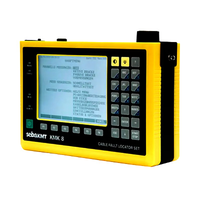
The Megger KMK8 AC and DC fault location bridge is designed to support professional cable fault diagnosis and electrical network maintenance, making the Megger KMK8 AC and DC fault location bridge Price in Bangladesh a relevant search for engineers and technicians looking for specialized fault-locating equipment. This instrument uses bridge measurement principles to help identify faults in cables and electrical circuits. It supports systematic troubleshooting by assisting technicians in determining fault locations, reducing unnecessary cable excavation, and improving maintenance efficiency.
The KMK8 is intended for fault location applications involving alternating current and direct current measurement methods. Bridge-based testing compares electrical values to help determine the position of a fault along a cable. Depending on the cable configuration and fault characteristics, these techniques can support the investigation of insulation faults, conductor faults, and other electrical irregularities. Appropriate test connections and correct measurement procedures are essential for obtaining meaningful results.
Cable faults can interrupt industrial operations, building services, communication systems, and electrical distribution networks. The Megger KMK8 supports troubleshooting activities by helping maintenance personnel investigate suspected cable defects. It can be useful in cable maintenance workshops, utility service operations, electrical contracting, and technical testing environments where locating a fault accurately is important. The selected measurement method should match the cable type and the nature of the suspected fault.
Accurate fault location helps maintenance teams concentrate their inspection efforts on the relevant cable section. By using suitable bridge measurement techniques, technicians can reduce guesswork, avoid unnecessary replacement work, and plan repairs more effectively. The KMK8 can form part of a structured cable diagnostic process, helping professionals investigate electrical problems and support maintenance decisions. Results should always be assessed alongside cable records, test conditions, and other available diagnostic information.
Effective cable fault location requires a clear understanding of the cable arrangement, accessible test points, conductor condition, and fault characteristics. Before testing, technicians should verify the cable configuration and select the appropriate AC or DC measurement procedure. Proper preparation and careful interpretation of readings can help improve diagnostic consistency. Users should follow the manufacturer's operating instructions and safety guidance throughout the testing process.
Specialized fault-locating equipment is valuable when electrical cables develop faults that are difficult to identify through visual inspection alone. A suitable fault location bridge can help technicians investigate electrical characteristics and estimate where a fault may be present. This information can support repair planning, reduce troubleshooting delays, and improve the management of cable infrastructure. The effectiveness of any bridge method depends on the fault type, cable characteristics, and test setup.
Electrical maintenance teams in factories, commercial facilities, infrastructure projects, and utility operations need dependable diagnostic procedures to maintain service continuity. The Megger KMK8 can be considered for applications where AC and DC bridge-based fault location methods are appropriate. Engineers should evaluate the instrument against their actual cable testing requirements and confirm compatibility with the network or cable system before use.
When selecting a cable fault location bridge, buyers should review the supported measurement methods, compatible cable types, operating requirements, connection arrangements, and available technical documentation. The instrument should be appropriate for the expected fault conditions and the working environment. It is also advisable to confirm the product's specifications, accessories, calibration requirements, and after-sales support with the supplier before making a purchasing decision.
In Bangladesh, electrical contractors, industrial maintenance teams, infrastructure operators, and technical service providers may require specialized equipment for investigating cable faults. The Megger KMK8 AC and DC fault location bridge is relevant to professionals seeking bridge-based diagnostic solutions for suitable cable testing applications. Buyers should consult a qualified supplier to verify product availability, technical suitability, documentation, warranty terms, and service support.
Using genuine Megger testing equipment provides access to manufacturer-specific documentation and technical guidance. Correct instrument handling, suitable test connections, and compliance with the manufacturer's safety instructions are important for dependable measurements. Since fault location procedures may involve hazardous electrical systems, testing should be carried out by trained personnel using the appropriate isolation procedures and protective equipment.
The Megger KMK8 AC and DC fault location bridge is a specialized instrument for professionals involved in electrical cable fault investigation and maintenance. Its AC and DC bridge-based approach can support systematic diagnosis when applied to suitable cable configurations and fault conditions. For engineering companies and maintenance professionals in Bangladesh, selecting appropriate fault location equipment can help improve troubleshooting procedures, repair planning, and the overall management of electrical networks.
The KMK 8 consists of the measuring modules:
Due to the graphical display, the easily operated menu and extensive help functions, the handling and operation of the KMK 8 is very easy. The displayed test results can be stored in the internal memory as a PDF or Excel file to transferred via.
Four instruments in one:
Active Bridge for accurate location of faults on cables with low interference voltages level.
Passive Wheatstone Bridge for location of faults on cables with high interference voltages level.
Graaf Fault Locator for accurate fault location on totally
Reflectometer (TDR) for the location of low impedance faults and cross talk between pairs The hand-held Cable fault locator KMK 8 is used to test the quality of telecom cables and to locate cable faults. The combined instrument provides several tools for the accurate location of DC and AC faults.
Remote Controllable Far end Devices:
MK 8 has a function for the remote control of a far end loop closing device. This feature allows just one person to perform measurements, which require the operation of the far end loop (e.g Küpfmüller).
Large Memory:
The test results can be stored in the internal memory and transferred to a PC. It is possible to view the results directly in the display and to print them from there. Alternatively the data can be viewed as table and transferred to the PC as PDF file. The results can also be converted into Excel format.
|
Test Category |
Available Methods / Features |
|---|---|
|
Resistance Measurements |
Loop resistance |
|
Resistance difference |
|
|
Insulation resistance |
|
|
Capacitance Measurements |
Cable capacitance |
|
Capacitive balance |
|
|
DC Fault Location Methods |
Murray, 3 Point |
|
Repeated Küpfmüller |
|
|
AC Fault Location Methods |
Interruption |
|
Repeated Küpfmüller |
|
|
Graaf Fault Location Method |
End-to-end Master-Slave measurement |
|
Fault location on completely wet cables |
|
|
TDR Measurements |
Single-pair measurements |
|
Double-pair measurements |
|
|
XTALK |
|
|
Comparison to memory |
|
|
AC-DC Voltage Measurements |
AC and DC voltage measurement |
|
Temperature Measurement |
Cable temperature measurement |
|
USB Ports for Result Transfer |
USB B device port for direct PC connection |
|
USB A host port for USB stick and indirect data transfer |
|
|
Indirect Data Transfer Advantage |
Allows users to transfer results using a USB stick without needing administrative rights to install a driver on their PC |
Automatic Test Sequences:
|
Specification |
Details |
|---|---|
|
Power Supply |
Internal rechargeable NiMH battery pack |
|
Operating Time |
Approximately 8 hours without backlight |
|
Charging Options |
100–240 V AC mains adapter or 12 V car battery with car adapter |
|
Charging Time |
Less than 3 hours in fast charging mode |
|
Display |
320 × 240 dot graphic LCD |
|
Mains Adapter Connector |
2.1 / 5.5 mm coaxial connector |
|
L1 and L2 Line Connectors |
4 mm banana sockets |
|
Ground Connector |
4 mm banana socket |
|
USB A |
USB 1.1 host port for USB stick |
|
USB B |
USB 1.1 device port for PC connection |
|
Overvoltage Protection Between a and b or Ground |
500 V DC, 350 V AC (input resistance greater than 5 kΩ) |
|
Longitudinal Voltage |
60 V AC |
|
Reference Conditions |
23 ± 5°C; relative humidity 45%–75% |
|
Normal Operating Conditions |
0°C to +40°C; relative humidity 30%–75% (less than 25 g/m³) |
|
Operating Limits |
−5°C to +45°C; relative humidity 5%–95% (less than 29 g/m³) |
|
Storage and Transport Conditions |
−40°C to +70°C; relative humidity up to 95% at +45°C (less than 35 g/m³) |
|
Test Result Memory |
50 results |
|
Cable Parameter Memory |
50 sets |
|
Dimensions |
224 × 160 × 75 mm |
|
Weight |
Approximately 1.8 kg, including battery pack |
|
Specification |
Details |
|---|---|
|
Measuring Range for Non-Loaded Cable |
16 m to 32 km at V/2 = 100 |
|
Result Evaluation |
Cursor and marker in metres |
|
Waveform Refresh Rate |
Approximately 4 times per second |
|
Zoom |
Up to 16× |
|
Fault Location Accuracy |
0.2% of range |
|
Resolution |
0.01 m |
|
Propagation Velocity for Non-Loaded Cables (V/2) |
45–149 m/μs |
|
VOP for Non-Loaded Cables |
30%–99% |
|
Propagation Velocity for Loaded Cables (V/2) |
1.2–30 m/μs |
|
VOP for Loaded Cables |
0.8%–20% |
|
Pulse Width for Non-Loaded Cables |
4 ns to 6 μs |
|
Pulse Width for Loaded Cables |
330 μs |
|
Pulse Amplitude |
1.3–12 Vpp into 120 Ω |
|
Line Connection Impedance |
120 Ω balanced |
|
Balance Control |
50–270 Ω |
|
Gain Control Range |
0–90 dB |
|
Gain Control Steps |
6 dB per step |
|
Distance-Dependent Amplitude Correction |
10 steps |
|
Specification |
Details |
|---|---|
|
DC Voltage |
Up to 400 V |
|
AC Voltage |
Up to 250 V RMS |
|
Voltage Accuracy |
±3% ± 1 V |
|
Frequency Range |
15–300 Hz |
|
Input Resistance |
2 MΩ |
|
Specification |
Details |
|---|---|
|
Measuring Range |
1 Ω to 10 kΩ |
|
Accuracy |
±0.3% ± 0.1 Ω |
|
Specification |
Details |
|---|---|
|
Loop Resistance Range |
10 Ω to 5000 Ω |
|
Accuracy |
±0.2% of Rs ± 0.2 Ω |
|
Specification |
Details |
|---|---|
|
Measuring Range |
10 kΩ to 300 MΩ |
|
Measuring Voltage |
100 V |
|
Accuracy |
±2% to 5% ± 1 kΩ |
|
Specification |
Details |
|---|---|
|
Measuring Range |
10 nF to 2 μF (up to 10 μF, depending on range or configuration) |
|
Measuring Signal |
11 Hz, 100 V |
|
Accuracy |
±2% ± 0.2 nF |
|
Specification |
Details |
|---|---|
|
Measuring Range |
10 nF to 2000 nF |
|
Measuring Voltage |
11 Hz, 100 V |
|
Accuracy of Lx/L Value |
±0.2% |
|
Specification |
Details |
|---|---|
|
Test Methods |
Murray, Küpfmüller, 3-point |
|
Loop Resistance Range |
1 Ω to 10 kΩ |
|
Fault Resistance Range |
Up to 100 MΩ |
|
Measuring Voltage |
100 V |
|
Accuracy Below 1 MΩ Fault Resistance |
±0.2% |
|
Accuracy from 1 MΩ to 5 MΩ |
±0.3% |
|
Accuracy from 5 MΩ to 25 MΩ |
±0.5% |
|
Accuracy from 25 MΩ to 100 MΩ |
±2% |
|
Accuracy Test Conditions |
Rs = 2 kΩ; Lx/L = 0.1 to 1 |
|
Specification |
Details |
|---|---|
|
Loop Resistance Measuring Range |
1 Ω to 10 kΩ |
|
Loop Resistance Accuracy |
±0.3% ± 0.3 Ω |
|
Insulation Resistance Measuring Modes |
Quick measurement and quality measurement |
|
Quick Insulation Measurement Range |
10 kΩ to 300 MΩ |
|
Quality Insulation Measurement Range |
Up to 10 GΩ |
|
Insulation Measuring Voltage |
100 V |
|
Insulation Accuracy: 10 kΩ to 50 MΩ |
5% ± 1 kΩ |
|
Insulation Accuracy: 50 MΩ to 100 MΩ |
10% |
|
Insulation Accuracy: 0.1 MΩ to 5 GΩ |
20% |
|
Insulation Accuracy: 5 GΩ to 10 GΩ |
30% |
|
Resistance Difference Loop Range |
1 Ω to 5000 Ω |
|
Resistance Difference Accuracy |
±0.2% of Rs ± 0.2 Ω |
|
Lx/L (Mk) Resolution for ΔR Below 10% |
1/10,000 |
|
Lx/L (Mk) Resolution for ΔR Above 10% |
1/1,000 |
|
Specification |
Details |
|---|---|
|
Test Methods |
Murray, Küpfmüller, 3-point |
|
Loop Resistance Range |
1 Ω to 10 kΩ |
|
Fault Resistance Range |
Up to 100 MΩ |
|
Measuring Voltage |
100 V |
|
Accuracy Below 1 MΩ Fault Resistance |
0.2% |
|
Accuracy from 1 MΩ to 5 MΩ |
0.3% |
|
Accuracy from 5 MΩ to 25 MΩ |
0.5% |
|
Accuracy from 25 MΩ to 100 MΩ |
2% |
|
Resolution of Lx/L (Mk) Value |
1/1,000 |
|
Accuracy Test Conditions |
Rs = 2 kΩ; Lx/L = 0.1 to 1 |
|
Specification |
Details |
|---|---|
|
Method |
Küpfmüller |
|
Loop Resistance Range |
1 Ω to 10 kΩ |
|
Fault Resistance Range |
Up to 25 MΩ |
|
Measuring Signal |
11 Hz, 100 V |
|
Accuracy Below 1 MΩ Fault Resistance |
±0.3% |
|
Accuracy from 1 MΩ to 5 MΩ |
±0.5% |
|
Accuracy from 5 MΩ to 25 MΩ |
±1.0% |
|
Resolution of M Value |
1/1,000 |
|
Accuracy Test Conditions |
Rs = 2 kΩ; Lx/L = 0.1 to 1 |
|
Specification |
Details |
|---|---|
|
Measuring Range |
10 nF to 2000 nF |
|
Measuring Voltage |
11 Hz, 100 V |
|
Accuracy of Lx/L Value |
±0.2% |
|
Resolution when Lx/L = 0.9–1.1 |
1/10,000 |
|
Resolution when Lx/L is below 0.9 or above 1.1 |
1/1,000 |
|
Specification |
Details |
|---|---|
|
Loop Resistance Range |
10 Ω to 10 kΩ |
|
DC Current Range |
5 μA to 1 A |
|
Accuracy for Current Above 10 μA p>
|
±0.3% to ±2% |
|
Specification |
Details |
|---|---|
|
DC Interference Voltage |
0 to 400 V |
|
AC Interference Voltage |
0 to 250 V RMS |
|
Loop Resistance Range |
1 Ω to 10 kΩ |
|
Insulation Resistance Mode |
Repeated measurement |
|
Insulation Measurement Time |
Approximately 3 seconds |
|
DC Current Range |
10 μA to 1 A |
|
Temperature Measurement |
−20°C to +60°C using a Pt 1000 temperature probe |
|
Specification |
Details |
|---|---|
|
Interference Voltage Range |
Up to 400 V DC and 250 V AC |
|
Voltage Test Results |
Vab, VaE and VbE |
|
Insulation Resistance Range |
10 kΩ to 300 MΩ |
|
Insulation Measurement Time |
Approximately 3 × 15 seconds |
|
Capacitance Range |
10 nF to 2000 nF |
|
Capacitive Balance Measuring Voltage |
11 Hz, 100 V |
|
Capacitive Balance Test Result |
Unbalance percentage (%) |
|
Specification |
Details |
|---|---|
|
Insulation Resistance Range |
10 kΩ to 10,000 MΩ |
|
Insulation Measurement Time |
Approximately 3 × 30 seconds |
|
Capacitance Range |
10 nF to 2000 nF |
|
Loop Resistance Range |
1 Ω to 10 kΩ |
|
Loop Resistance Accuracy |
±0.3% ± 0.1 Ω |
|
Resistance Difference Loop Range |
10 Ω to 5 kΩ |
|
Resistance Difference Resolution |
1/1,000 |
No resources available for this product.
No reviews yet. Be the first to review this product!
Related Products
Discover your related products for more professional testing and measurement solutions.


